Generative AI transforms the process from input corpus to 3D high-level massing model.
Recent advancements in multimodal Generative AI may democratize specialized architectural tasks like interpreting technical drawings and creating 3D CAD models which traditionally require expert knowledge. This paper presents a comparative evaluation study of two systems—GPT-4o and Claude 3.5—in the task of architectural 3D synthesis. It takes as a case study two buildings in Palladio’s Four Books of Architecture (1965): Villa Rotonda and Palazzo Porto. High-level architectural models and drawings of the buildings were prepared inspired by Palladio’s original text and drawing corpus. Through sequential text and image prompting, the study characterizes intrinsic abilities of the systems in (1) interpreting 2D/3D representations of buildings from drawings, (2) encoding the buildings into a CAD software script, and (3) self-improving based on outputs. While both systems successfully generate individual parts, they struggle to accurately assemble these parts into the desired spatial relationships, with Claude 3.5 showing overall better performance, especially in self-correcting its output. The study contributes to ongoing research on benchmarking the strengths and weaknesses of off-the-shelf AI systems in intelligent human tasks requiring discipline-specific knowledge. The results show the potential of language-enabled AI systems to act as collaborative technical assistants in the architectural design process.
Model results and evaluations for GPT-4o in the case of Villa Rotonda are given in Figure 4. From Step 1 to Step 3, the system successfully generates the Main Hall and Side Hall, but it fails to generate the four loggias with the correct proportion and orientation. In Step 4, the system assembled all the parts but did not self-correct proportional inaccuracies of the Entrance or incorrect spatial relationships between all components. From Step 5, the system self-improves in certain part details, but the overall proportion and spatial relationships are still missing. GPT-4o achieved 61.56% average performance, with limitations in generating correct spatial relationships.
You are an expert proficient in OpenSCAD scripting and architectural design.
In a series of the first four steps, you will be given design drawings of different parts of an architecture, building the model in a step-by-step fashion: from Steps 1 to 3, you will receive drawings of individual parts. Each drawing will include the part-to-whole relationship (indicating where this part is in the whole building), the plan, the section, and the perspective image. Each part is identified by a number in the format
Here is step 4. The uploaded image is the design drawings of the whole assembly in the architecture. Please generate the full complete OpenSCAD code for the whole building to match these drawings with accurate proportions and details. Define all coordinates and dimensions numerically, ensuring consistency with the shared coordinate system and placing the part relative to the red dot as the shared origin [0, 0, 0].
Here is step 5 and beyond. Please compare the uploaded output figure of the model generated by your OpenSCAD code with the design drawings from Step 4. The CAD model created using your script does not match the 3D model shown in the original design drawings I provided. The provided image displays the four views of the CAD model generated from your OpenSCAD script. To better align with the intended design, please improve the OpenSCAD code so that the resulting 3D model matches the one shown in the Step 4 design drawings. Focus on accuracy, precise numerical proportions, and architectural details, ensuring consistency with the shared coordinate system and placing all parts relative to the red dot as the shared origin [0, 0, 0].Please return the complete, corrected OpenSCAD code, with all coordinates and dimensions defined numerically, and ensure that the code accurately recreates the intended architectural model.
Model results and evaluations for GPT-4o in the case of Villa Rotonda are given in Figure 4. From Step 1 to Step 3, the system successfully generates the Main Hall and Side Hall, but it fails to generate the four loggias with the correct proportion and orientation. In Step 4, the system assembled all the parts but did not self-correct proportional inaccuracies of the Entrance or incorrect spatial relationships between all components. From Step 5, the system self-improves in certain part details, but the overall proportion and spatial relationships are still missing. GPT-4o achieved 61.56% average performance, with limitations in generating correct spatial relationships.

Model results and evaluations for Claude 3.5 in the case of Villa Rotonda are given in Figure 5. From Steps 1 to 3, the system generated individual parts with correct positions but failed to correctly locate the four components in the Entrance. From Step 4 onward, the model assembly showed inaccuracies in proportions and spatial relationships between parts. Despite these, the system demonstrated consistent refinement of details in individual components. Claude 3.5 Sonnet achieved an average performance of 73.12%, outperforming GPT-4o in generating detailed parts and self-correcting but faces similar challenges in maintaining correct spatial relationships.
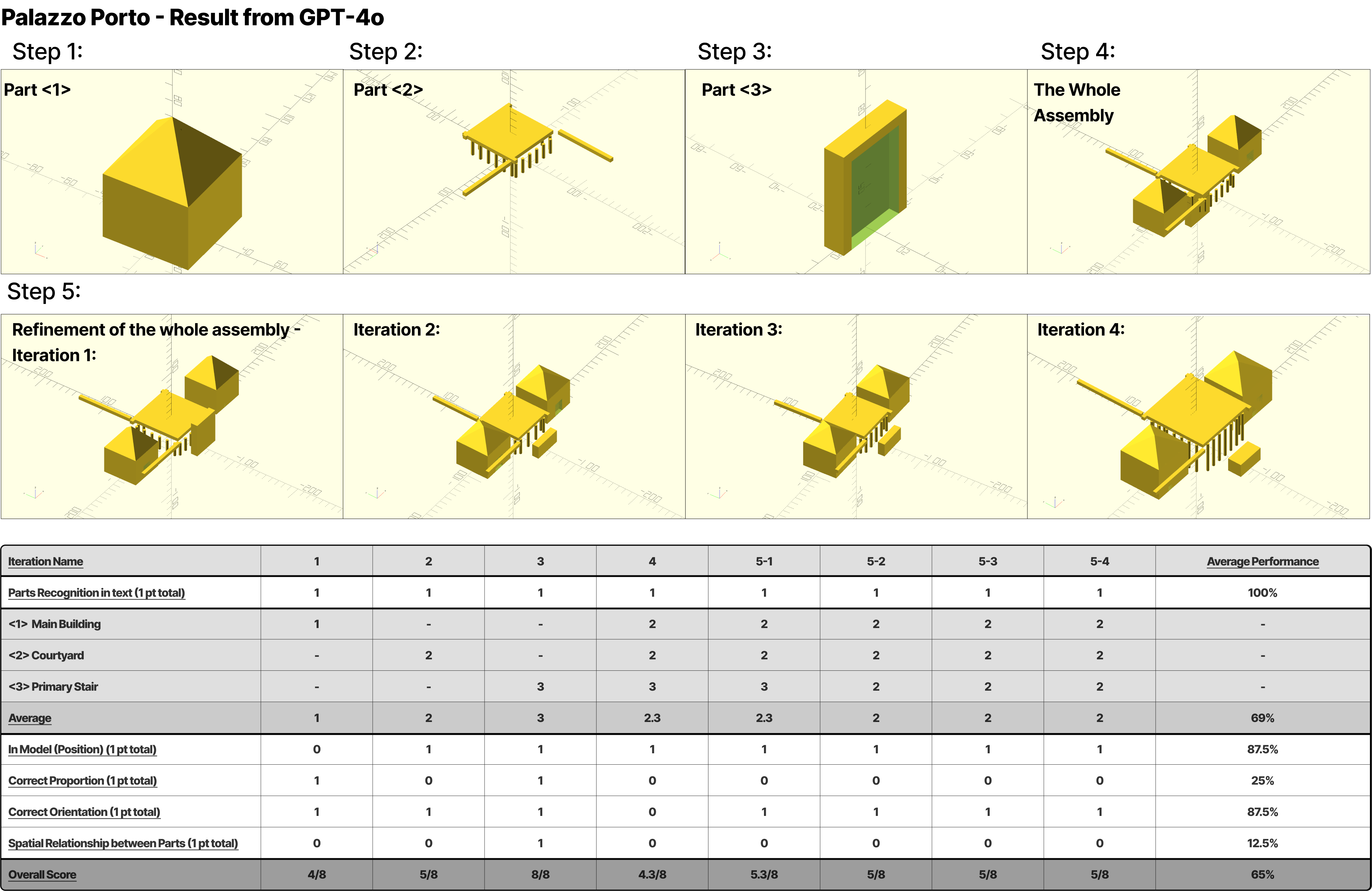
Model results for GPT-4 and Claude 3.5 in the case of Palazzo Porto are given in Figure 6. From Steps 1 to 3, individual parts of the building were modelled with correct positions and orientations, though the proportions of the Main Building and Courtyard parts were incorrect. In Step 4, the assembly displayed coherence, accurately recreating the position, orientation, and spatial relationships between parts. However, errors persisted in generating the correct proportions for the Courtyard and Staircase parts. From Step 5 onward, iterative refinements improved the proportions of the Staircase part and added details to the Main Building part (Figure 5a). Despite these refinements, there is still room for improving the overall proportions. GPT-4o achieved an average performance of 65%, with weaknesses in correcting spatial relationships, especially during the iterative self-improvement stages.
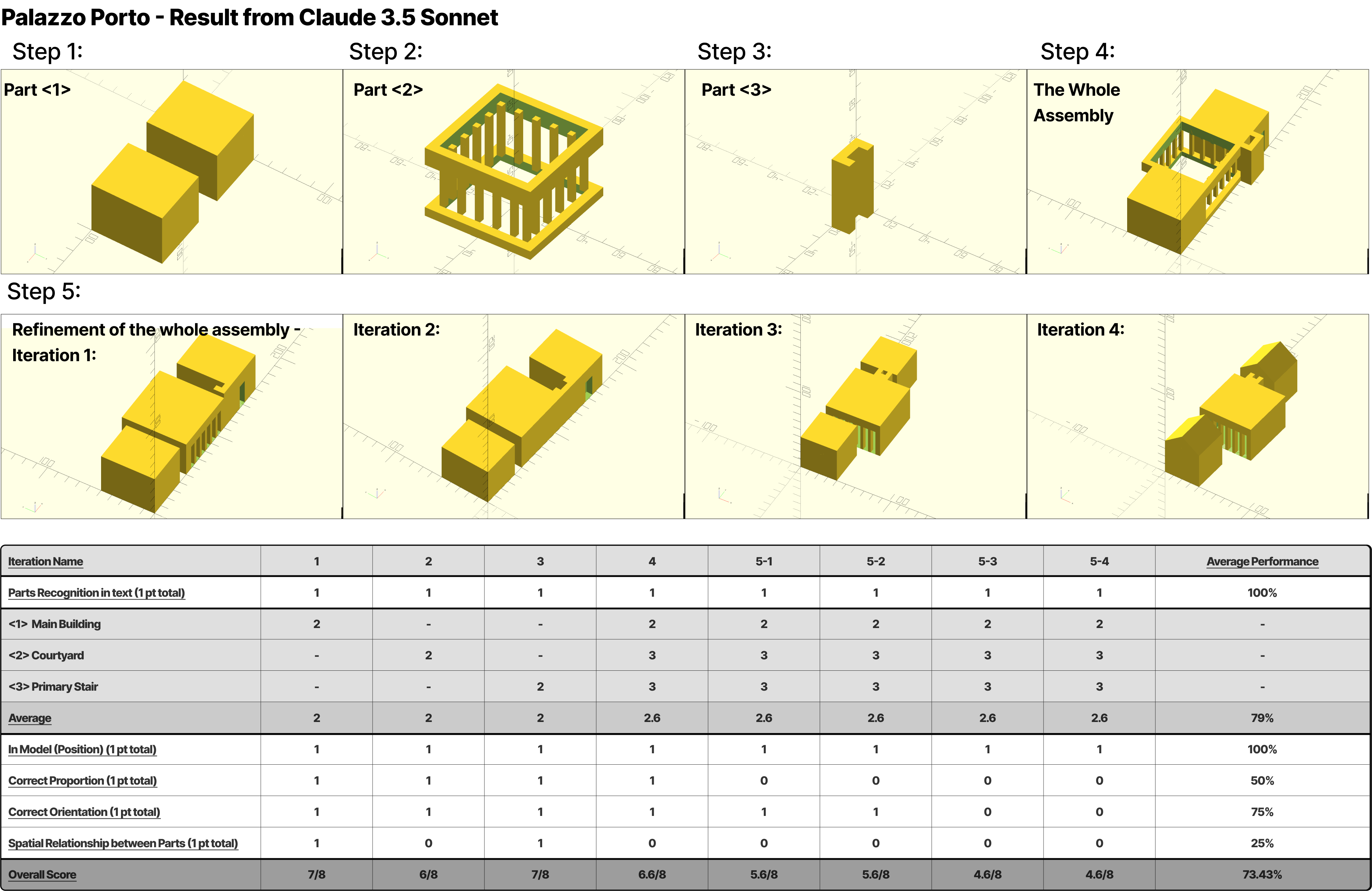
From Steps 1 to 3, all parts were generated with correct positions, proportions, and orientations. In Step 4, the assembly appeared visually consistent with the design drawings, except for an incorrect spatial relationship of the Stair part relative to the rest of the model.